Surveillance
The trace is the surrounding bracket that contains the zone, the device fleet, the profile and the holds the notification together. This monitoring then determines whether and which alarms a Notification, who will be notified and whether there will also be escalations gives.
Create different monitoring and alarm scenarios for different monitoring and alarm scenarios Traces. Each trace can be activated or deactivated; several traces can also be Traces are active at the same time and the different traces may also contain the the same or an overlapping set of your devices.
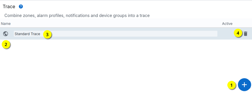
To create a new trace, click on the “+” symbol in the “Trace” or “Monitoring” menu click here. Existing traces can also be changed here by selecting the name .
With you can delete a monitoring and with open the monitoring card. Is the Globe symbol is green, monitoring is active.
Attachment/processing
If a new monitoring system is created or an existing one is changed, the Window with the details.
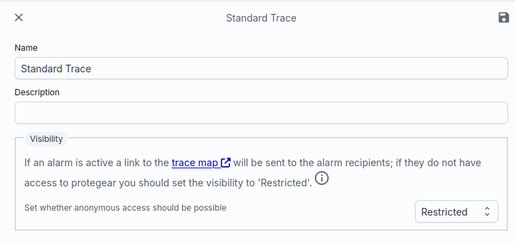
You can enter the name and a description in the header data. Additionally a monitoring also has a visibility that is normally set to Restrictive is set. This means that monitoring can also be sent to unauthenticated users be released. You have the following options here:
- Restrictive: No data is displayed via the link shown, unless an alarm is active. Then the link shows a monitoring card with the devices included in the monitoring and their status.
- Public: The devices and their status are displayed via the displayed link displayed. Anyone who knows the link can see the data.
- Private: No data is displayed via the displayed link, either, when an alarm is active. Only registered users can access the Protegear Console to view the monitoring map. Use the option to create your own Users in the platform if you want to use these users as alarm recipients enter.
The Restrictive mode is preset. When an alarm is triggered the alarm recipients are sent a link to this monitoring card and can then see the data without logging in again. As soon as the alarm is cancelled, the Release of data cancelled promptly.
Attention
In addition to the device positions, the monitoring card also contains the alarm data and geofences (home zone) and also the settings you entered in Settings Information (possibly health data). This can be very private data in total. Please be careful, to whom you make this data accessible.
Details
Each monitoring system is linked to a fleet, a zone and a profile. The fleet defines which devices are included in the monitoring. The zone is used to define areas defined in which the monitoring pauses (pause zones), triggers an alarm (danger zones) or where it is safe to stay. In the profile, you also specify to define the alarm functions and their parameters.
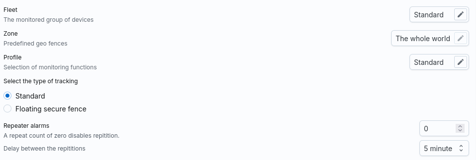
All three values are lists from which you can choose. Normally your System with one standard fleet, one standard zone and one standard profile equipped. However, you can also change these values or create additional ones and then link in the trace.
Note
The zone “The whole world” is a special zone in which the whole world is defined as a safe zone.
Tracking type
With the zone definition, a monitoring system has several geofences that are statically are defined in a map. However, it can also be useful to define zones dynamically to move. This is realised with the Floating tracking type. You use this to create determines that a safety zone is created around a specific device, i.e. it is this is a round zone that is moved along with this mother device.
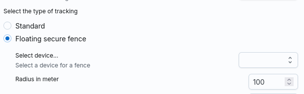
The zone is a safe zone by default. Use this feature, for example, for to be alerted by a ship if the dinghies move too far away.
Alarm repetitions
Alarms can be repeated after certain time intervals. This setting is normally switched off, but you can activate it.
Alarm table
While the supported alarm functions are defined in the profile, the Trace to link such alarms with notifications. Create to do this, open a notification matrix and select the relevant nodes:
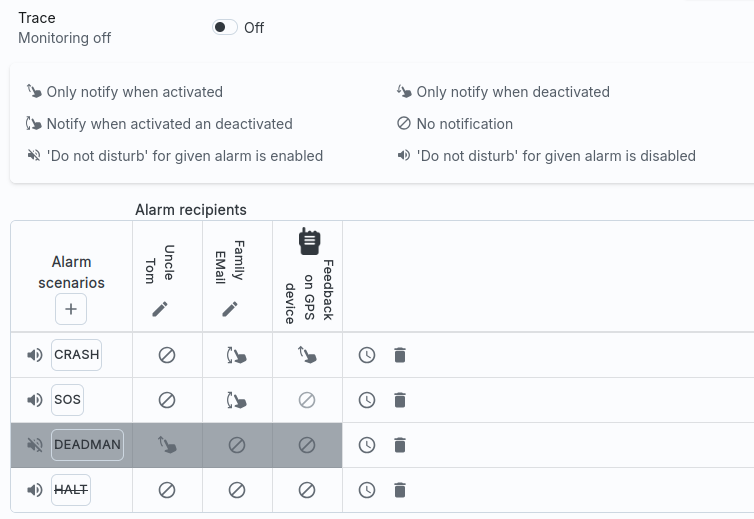
The alarms are activated with the Trace switch. Only when the alarm is switched on, the trace is active. Alarms are then sent to the corresponding channels sent.
The matrix consists of one column each for the notification channel and a line for the alarm scenario. You can use the “+” symbol to add further scenarios add a scenario. To do this, click on the “+” and then directly on the scenario name. A list of possible alarm scenarios then appears.
If these are not supported by your selected alarm profile, then these are crossed out. You can still insert them in the matrix and as long as this alarm is not activated in the selected profile, it is also not triggered.
You can also use the mute button ( ) to mute certain alarms in the matrix
mute alarms. This allows you to deactivate ad hoc alarms without the profile
or change the matrix. If you want to reactivate the alarm, deactivate
you can switch off the mute function.
) to mute certain alarms in the matrix
mute alarms. This allows you to deactivate ad hoc alarms without the profile
or change the matrix. If you want to reactivate the alarm, deactivate
you can switch off the mute function.
The last column is always the feedback of the alarm on the device, provided that the device supports this (e.g. not possible with the SmartSole). This feedback can the device can be operated via an acoustic signal and/or a vibration or a light signal.
Finally, you can also limit the duration of an alarm scenario by setting the
Clock  at the end of a line. You can then enter a time period
in which the alarm can be triggered. If the alarm occurs outside
of this period, it is ignored.
at the end of a line. You can then enter a time period
in which the alarm can be triggered. If the alarm occurs outside
of this period, it is ignored.
If an alarm scenario is no longer required, it can be deleted with from can be removed from the matrix.
The alarm matrix consists of one line each for a notification and dynamic columns that can be added using the “+” symbol. Each column represents an alarm that can be generated with the profile. If the alarm is deactivated, it is shown crossed out in the matrix.
Operation on the device
Depending on the end device, alarms can be cancelled by various actions on the device:
- If the device has an SOS-CANCEL button or action, you can use it to cancel all alarms exit. If you have set the MUTE function in the profile, then no more automated alarms are triggered for the specified time.
- If the device has START/STOP buttons, you can use the STOP action to stop almost all End alarms; only the manually triggered SOS alarms must still be cancelled with exit *CANCEL*. Please note that this also switches you to Pause mode i.e. no new alarms are activated until you press START again operate.
- If the device has the option to start a PAUSE, almost all alarms are also cancelled is cancelled (except SOS). In contrast to STOP, Alive, for example, continues to send tracking data to our system, so that the pause mode for this action is cancelled by exiting a Pause zone can be ended automatically (this is not mandatory for STOP) given)
- If the device also sends POWER-ON/OFF events, you can also simply switch the device off to switch off all alarms (incl. SOS).
Please note your settings in the profile for the PAUSE function. If there set so that the device automatically switches to pause mode when it switches off not moved for a period of time, this can cause the alarms to switch off unintentionally effect.
Escalations
SmartSafety supports a two-stage alarm model. The first stage of the An alarm is triggered when one of the alarm functions in the profile strikes. This The alarm can then be assigned to a notification via the alarm matrix.
An alarm remains open until the reason for the alarm no longer exists. This is how an SOS is valid until the device sends a CANCEL. With automatic Alarms, on the other hand, must be terminated by the server. For example, in the case of a ZONE alarm, the Transmit a new position to the device so that this alarm is cancelled.
However, if an alarm remains open, the second stage of the alarm can be triggered called *escalation*.
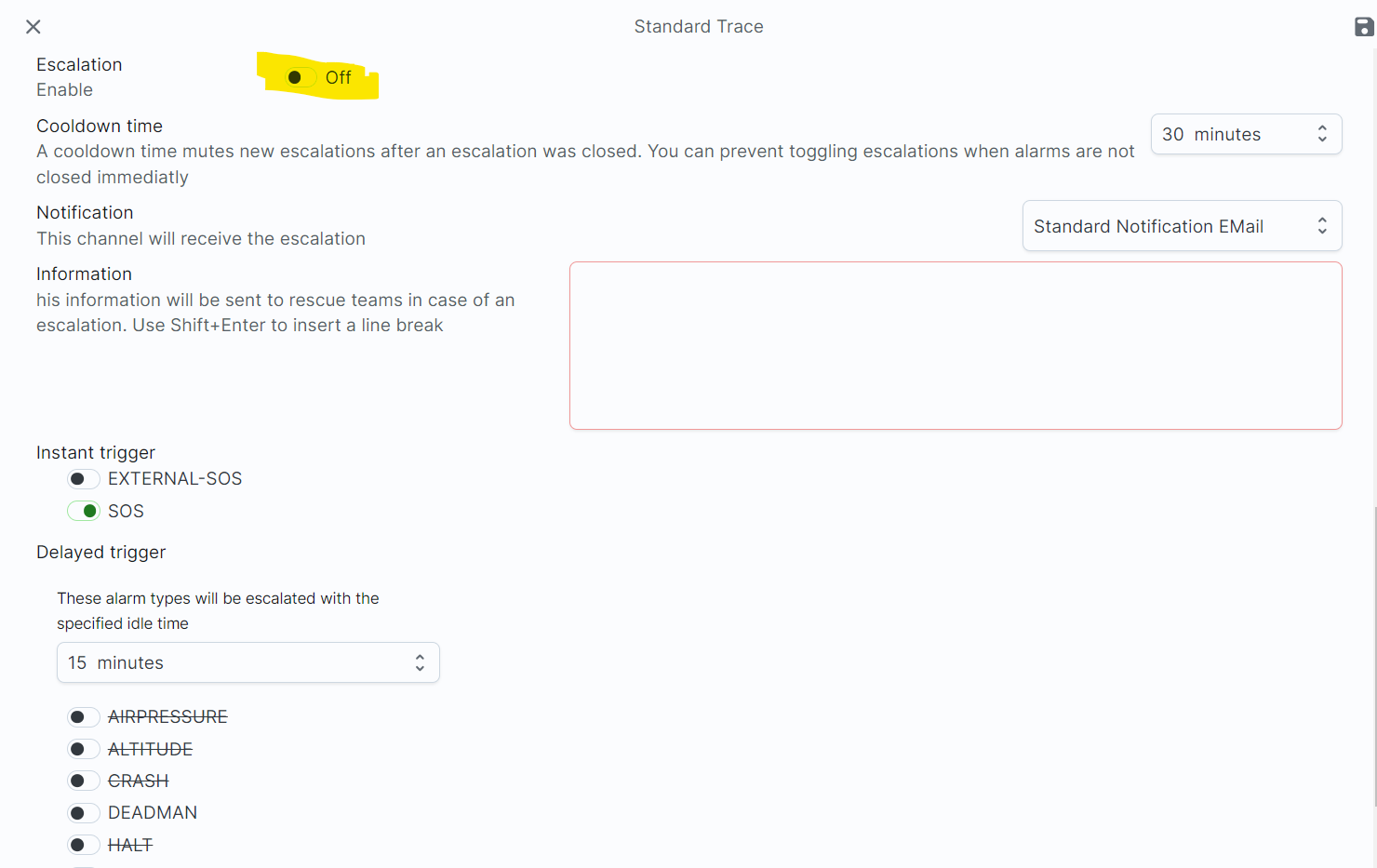
The escalation configuration distinguishes between Instant and Delayed Escalations. The alarms configured in the Instant escalation field immediately trigger an Trigger escalation processing as soon as this alarm occurs.
In contrast, delayed escalations are executed with a delay; the delay time is defined in the Idle time list. Only when a Delayed Alarm reaches this time period is active for a long time, this alarm is escalated.
Each escalation has a cooldown time, i.e. when an escalation has ended, the no new escalation is started during this period. A user can escalate through a CANCEL event always ends an escalation; such an event is therefore a signal to a rescue unit that everything is OK. However, as alarms may remain open directly (e.g. a ZONE alarm will always remain open or reopened as long as the Position does not change), a cool-down can thus make it possible to end an escalation although the alarm is still not closed.
Info
If the alarm situation is not fundamentally changed, after the cool-down time the Escalation reopened. You can activate the MUTE function in the profile; if the device then sends a CANCEL, the alarm is cancelled and for the new alarm is no longer triggered after the time stored in the profile.
Finally, the escalation contains additional information as free text as well as the notification channel to be used. The list also contains an entry for Focuspoint International, which can lead to an error message:
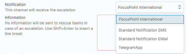
In such a case, you must have your devices activated for Focuspoint Rescue. Take please contact us.